Skip to content

What Is the Vacuum Brazing Process in 2026?

In 2026, the Vacuum Brazing Process remains a precise way to join metals without exposing them to air. Components sit inside a sealed furnace, where the chamber is evacuated and the temperature rises under controlled conditions. A thin layer of filler metal melts, flows into the narrow joint, and bonds the parts as they cool. The result can be clean and strong. But it is not automatic.

Joining researcher David P. DuPont’s field offers a useful principle, paraphrased rather than presented as a direct quotation: “Reliable joints depend on preparation, fit, and controlled heat—not filler metal alone.” That reminder matters on the shop floor. A fingerprint, uneven gap, or poorly chosen heating cycle can weaken a joint that looks sound from the outside. Vacuum brazing reduces oxidation; it does not erase design or preparation errors.

This guide explains how the process works, which materials and fillers are commonly used, and what engineers monitor during a furnace cycle. It also examines advantages, limitations, quality checks, and practical applications. The details matter. A small gap can change how filler metal flows, while furnace uniformity affects many parts at once. Not every assembly suits vacuum brazing, and calling it universally superior would be careless. The useful question is more specific: when does this process provide dependable joints for a particular design?
What Is the Vacuum Brazing Process in 2026?

What Vacuum Brazing Is and How It Joins Materials

Vacuum brazing joins metal parts by melting a filler alloy between them while the base materials remain solid. In a sealed furnace, low pressure limits oxygen and surface oxidation, often allowing flux-free joints. Heat draws the molten filler through narrow gaps by capillary action. The fit matters: a gap that is too wide can leave a weak or incomplete joint. AWS A3.0 terminology places brazing above 450°C, a useful distinction from soldering, not a universal process setting. The filler alloy and base metals determine the actual temperature. Small details count.

In 2026, manufacturers use vacuum brazing for assemblies such as stainless-steel heat exchangers and nickel-alloy components, where clean joints and repeatable heating are important. The ASM Handbook’s coverage of brazing describes how joint clearance, material compatibility, and thermal cycles affect results. A vacuum furnace can reduce contamination, but it cannot correct poor part preparation. Even a fingerprint or uneven gap may compromise wetting. This is easy to underestimate.

Tips: Degrease parts, check clearances, and support thin sections before loading. Use a trial coupon when materials or filler alloys change. Record the furnace cycle, then inspect the joint for voids or incomplete filler flow. These checks take time, but skipping them is a gamble.
How Vacuum Conditions Affect the Brazing Process

What Is the Vacuum Brazing Process in 2026?

How Vacuum Conditions Affect the Brazing Process

Vacuum brazing joins clean, closely fitted metal parts by melting a filler alloy without melting the base metals. In a furnace, reduced pressure limits oxygen around the hot assembly. That matters because surface oxides can block filler flow and leave weak, uneven joints. The AWS Brazing Handbook discusses atmosphere control as a key part of brazing quality. Vacuum helps, but it cannot remove every contaminant or fix poor joint clearance.

Pressure gives a useful reality check. At 10⁻⁴ torr, an ideal-gas estimate puts the remaining gas density at roughly 3 × 10¹² molecules per cubic centimetre at room temperature—millions of times below air at sea level. That estimate is not a guarantee of a clean joint: leaks, outgassing, and furnace loading can change conditions during heating. I would not treat the pressure reading alone as proof of success. A bright-looking part can still hide incomplete filler flow.

Tips: Check parts for oil and trapped moisture before loading. Use thermocouples near representative joints, not only at the furnace wall. Record pressure through the full heating cycle; a sudden rise may signal outgassing or a leak. For process limits, consult the AWS Brazing Handbook and validate settings with sample joints.

The Main Steps in a Vacuum Brazing Cycle

The Main Steps in a Vacuum Brazing Cycle

A vacuum brazing cycle starts before the furnace door closes. Technicians remove oil, oxide, and fingerprints from the joint surfaces, then place filler metal precisely at the seam. Parts are fixtured to preserve clearance as they expand. Too much restraint can distort thin sections; too little can let components shift. Small details matter.

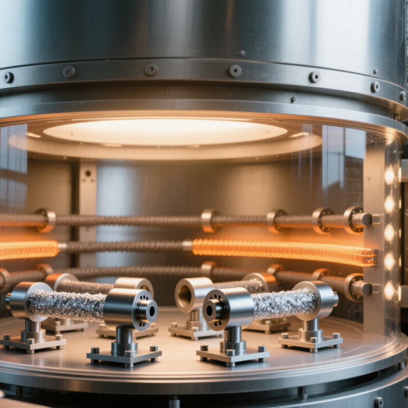
The furnace is sealed and evacuated to reduce oxygen and limit oxidation. Operators then heat the assembly at a controlled rate, allowing trapped gases to escape before the filler melts. At the brazing temperature, the filler flows through the joint by capillary action. The hold time depends on the alloy, part mass, and joint design—not one universal recipe. SAE AMS2750H specifies temperature-uniformity classes; its Class 2 allowance is ±10°F (about ±5.6°C). That figure describes furnace uniformity, not an acceptable joint-temperature variation.

After the hold, the load cools under vacuum or a controlled backfill, according to the materials and process. Rapid cooling may increase distortion, while slow cooling can affect cycle time. Once unloaded, inspectors check for incomplete flow, visible voids, and dimensional changes. In practice, the cooling step is often underestimated. It deserves the same attention as peak temperature.

What Is the Vacuum Brazing Process in 2026?

Representative temperature profile for an aluminum vacuum brazing cycle. Actual temperatures and timings depend on the base alloy, filler metal, part geometry, and furnace setup.

Cycle overview: Parts are cleaned and loaded, the chamber is evacuated, and the furnace heats the assembly to the filler-metal brazing range. A brief hold allows the filler to flow and form joints; controlled cooling then solidifies the joints before the parts are unloaded.

Suitable Materials, Filler Metals, and Applications

Vacuum brazing joins clean, closely fitted parts by melting a filler metal without melting the base materials. It suits stainless steel, nickel alloys, and selected copper or aluminum alloys. Some titanium alloys can also be brazed, but they need carefully controlled conditions and qualified procedures. Fit matters. A narrow, even joint gap helps the molten filler flow through the seam by capillary action.

Filler choice depends on the base metals, service temperature, and joint strength required. Silver-based fillers work with many steels and copper alloys at relatively low brazing temperatures. Nickel-based fillers suit stainless steels and nickel alloys exposed to higher temperatures or corrosive environments. Aluminum-silicon fillers are used for compatible aluminum assemblies, including heat exchangers. Copper-based fillers may suit some steel joints, but their temperature and compatibility limits matter. Not every alloy. Fillers containing volatile elements can evaporate under vacuum, so composition and furnace conditions need careful review.

Typical applications include compact heat exchangers, fuel-system components, vacuum-tight assemblies, and complex parts with many joints. The process can create clean joints with little flux residue, which is useful when parts have internal passages. Yet a bright surface does not prove a sound bond. Poor fit, trapped contamination, or an unsuitable filler can leave weak or incomplete joints, even when the finished assembly looks acceptable. Test samples and inspection should reflect the part’s actual materials and operating conditions.

What Is the Vacuum Brazing Process in 2026? — Suitable Materials, Filler Metals, and Applications

Material or Joint Common Filler-Metal Type Indicative Brazing Temperature Typical Applications Key Process Considerations
Stainless steel Nickel-based alloys, such as Ni-Cr-Si or Ni-Cr-Si-B; silver-based fillers may suit lower-temperature applications Approximately 800–1,200°C, depending on filler composition and base metal Heat exchangers, manifolds, filters, and fluid-handling assemblies Clean surfaces and controlled joint clearance are important. Boron-containing fillers can form brittle borides, so filler choice and joint design should be qualified for the service conditions.
Aluminum and aluminum alloys Aluminum-silicon fillers, commonly near-eutectic compositions Approximately 580–620°C Automotive and industrial heat exchangers, cold plates, and lightweight assemblies Aluminum oxide is difficult to remove; vacuum level, magnesium content, surface preparation, and furnace conditions are critical. Excessive temperature or dwell can cause filler erosion or base-metal distortion.
Copper and copper alloys Silver-copper or copper-based fillers; selection depends on the base alloy and required service temperature Approximately 700–1,100°C Electrical assemblies, heat-transfer components, and vacuum-compatible hardware Choose a filler whose brazing range is below the base metal’s solidus. Joint clearance and thermal expansion should be considered, particularly in dissimilar-metal joints.
Nickel-based alloys and superalloys Nickel-chromium-silicon or nickel-chromium-silicon-boron fillers Approximately 1,050–1,200°C Turbine and aerospace components, high-temperature heat exchangers, and complex assemblies The filler must melt below the base alloy’s solidus. High-temperature exposure can affect the base metal’s properties; filler selection, dwell time, and post-braze treatment may require qualification.
Titanium and titanium alloys Titanium-, zirconium-, copper-, or nickel-containing fillers designed for titanium joints Often approximately 850–1,000°C, depending on the alloy system Aerospace structures, instrumentation, and specialized lightweight components Titanium is highly reactive at elevated temperature. A clean, well-controlled vacuum cycle is essential, and filler compatibility and joint strength must be verified for the application.
Ceramic-to-metal joints Active brazing fillers containing a reactive element such as titanium, often in a silver-copper matrix Often approximately 800–900°C; composition-specific Electrical feedthroughs, sensors, vacuum components, and ceramic packages The active element promotes wetting of the ceramic. Ceramic metallization, joint geometry, and the different thermal expansion of ceramic and metal are important design factors.

Typical Vacuum Brazing Cycle

Stage What Happens Purpose
1. Preparation and fixturing Parts are cleaned, assembled with filler metal, and positioned with suitable joint clearance. Reduces contamination and supports consistent filler flow and alignment.
2. Evacuation and heating The furnace is evacuated and the assembly is heated according to a controlled cycle. Limits oxidation and removes gases and volatile contaminants from the hot zone.
3. Brazing and filler flow The assembly reaches a temperature above the filler’s liquidus but below the base metal’s solidus; molten filler flows into the joint by capillary action. Forms the metallurgical joint without melting the base components.
4. Cooling and inspection The assembly is cooled under controlled conditions, then inspected and tested as required. Helps manage distortion and verifies joint integrity for the intended service.

Note: Temperature ranges are indicative, not universal set points. The correct cycle depends on the specific base-metal grade, filler composition, joint design, furnace capability, and applicable qualification requirements. Vacuum brazing is generally best suited to clean, properly designed joints that can be assembled and heated uniformly.

Key Advantages and Limitations of Vacuum Brazing in 2026

What Is the Vacuum Brazing Process in 2026? Key Advantages and Limitations of Vacuum Brazing in 2026

Vacuum brazing joins metal parts by heating them with a filler alloy inside a low-pressure furnace. The filler melts, flows through the joint, and bonds the surfaces as the assembly cools. With no flux residue, finished parts can emerge clean and ready for inspection. ASM Handbook, Volume 6A, describes vacuum brazing as suited to assemblies that need controlled heating and clean joints.

That control has trade-offs. Vacuum furnaces require substantial equipment investment, and chamber dimensions limit the size of each load. Some metals can evaporate or react at high temperatures, so alloy choice and furnace conditions matter. Joint fit is critical, too: the AWS Brazing Handbook gives typical clearance guidance around 0.001–0.005 inches (25–127 micrometres), though the right gap depends on materials and filler. A gap that looks tiny on a drawing can still cause incomplete flow. Not every production line needs this level of cleanliness.

Tips: Check joint clearance on actual parts, not just drawings. Keep test coupons in the load. They help reveal uneven heating before a full batch is at risk. Vacuum brazing is precise, but setup errors still happen.