Skip to content

What Is an Intelligent Pole and How Does It Work?

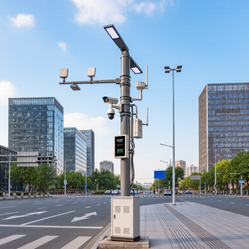
An Intelligent Pole is more than a streetlight with a network connection. It can combine LED lighting, sensors, wireless radios, cameras, and environmental monitors on one street-side structure. Urban designer and MIT professor Carlo Ratti has described the connected city as “the internet of things.” His phrase offers a useful lens, though it is not a claim about poles alone. The key idea is connection.

In operation, sensors collect local data, such as traffic movement, air conditions, or light levels. A controller processes readings and can adjust lighting or send information to a city platform. Network equipment may also support public connectivity and nearby devices. The pole becomes both a physical fixture and a point in a larger digital system. Its exact capabilities depend on the hardware, software, network, and services installed.

The benefits are practical when systems are well planned: better visibility at night, more responsive maintenance, and useful data for managing streets. But the promise is not automatic. Poor sensor placement, weak connectivity, or unclear data practices can limit results. And a crowded pole can be harder to maintain. That detail matters. This article explains what an Intelligent Pole is, how its components work together, and where its real-world value—and limitations—appear. It also considers why installation, interoperability, and ongoing upkeep deserve attention alongside the technology itself.

What Is an Intelligent Pole and How Does It Work?

What Defines an Intelligent Pole: Structure, Devices, and Service Layers

An intelligent pole combines a load-bearing structure with power, communications, and service equipment. Its steel shaft, foundation, access panels, and mounting brackets must support wind loads and allow safe maintenance. Inside, protected cabling and power controls connect devices without turning the pole into an overcrowded cabinet. Small details matter: drainage, heat, corrosion, and room for future upgrades.

The device layer may include an LED luminaire, traffic or air-quality sensors, public Wi-Fi, and connectivity equipment. Cameras or charging points can be added where site needs justify them. The service layer links these devices to management software, where operators monitor faults, adjust lighting, and review sensor data. The scale of urban demand is clear: UN DESA’s World Urbanization Prospects 2018 projects that 68% of people will live in urban areas by 2050. GSMA’s The Mobile Economy 2024 reports 1.6 billion 5G connections worldwide at the end of 2023. These figures describe broader urban and network trends, not guaranteed demand for smart poles.

Still, integration is often messier than diagrams suggest. Devices may use different networks, power budgets, and maintenance schedules. A useful design therefore defines who owns each data stream, how faults are reported, and how systems remain secure. ITU-T Recommendation Y.4903 offers city-level indicators for assessing smart, sustainable-city performance; it does not certify an individual pole. That distinction matters. A pole can collect data, yet poor placement or upkeep can make those readings less useful.

What Is an Intelligent Pole and How Does It Work?

Representative Radio Frequencies and Their Free-Space Wavelengths

Intelligent poles combine a supporting structure with devices such as wireless access points, cellular radios, cameras, and environmental sensors. Power and communications equipment connect these devices to service layers for connectivity, sensing, and data management. The chart shows representative radio-frequency points; wavelengths are calculated in free space using wavelength = speed of light ÷ frequency. Actual bands and deployments vary.

How Power and Controls Connect: NEMA ANSI C136.41’s 7-Pin Interface

An intelligent pole is more than a streetlight on a post. It can combine lighting, sensors, and controls in one outdoor system.

The NEMA ANSI C136.41 seven-pin interface provides a defined connection between a luminaire and a compatible control device. Three larger contacts typically carry line, neutral, and switched power. Four smaller contacts support dimming and other low-voltage control connections, depending on the equipment.

That matters.

A controller fitted to the socket can adjust light output using schedules, photocell readings, or remote commands. The interface gives power and control signals a shared physical connection, while the wider communications system handles network access.

A seven-pin socket alone does not make a pole connected or intelligent. The controller and luminaire must support compatible functions, and settings need proper commissioning.

The diagram looks clean; field wiring rarely does. Moisture, loose contacts, and mismatched dimming settings can cause flicker or prevent expected control.

Technicians should check the wiring plan and verify operation at the pole, not rely only on a parts list.

It is a practical interface, but not a magic one.

How Sensors Send Data Through Edge Systems and Communications Networks

An intelligent pole turns street-level equipment into a connected sensing point. Cameras, air-quality monitors, and traffic sensors capture conditions such as a queue forming or fine dust rising. An edge computer nearby checks these readings, removes duplicates, and flags urgent events before sending selected data onward. Less urgent records can travel in batches. The pole may use fiber, cellular service, or a local wireless link to reach a city platform. The route depends on coverage, power, and how quickly a response is needed.

The scale is growing. IoT Analytics’ State of IoT—Summer 2024 report estimated 18.8 billion connected IoT devices worldwide in 2024. That volume makes local filtering useful: raw video need not cross the network when a short event alert will do. Still, edge processing is not magic. A poorly placed sensor can report a misleading reading, and weak connectivity can delay even well-processed data. Operators should check timestamps, device health, and network interruptions before acting on a dashboard.

Tips: Test one sensor in real street conditions before expanding. Compare its readings with a trusted reference, and record signal strength during busy hours. Small gaps matter. A quiet network test may not reflect a crowded evening.

How Automated Control Works: From Detection to Analysis and Response

An intelligent pole links sensors, lighting controls, and computing equipment to monitor nearby conditions. Its automated control process begins with detection. A camera may identify a vehicle entering a restricted parking area, while an air sensor measures particulate levels near a busy road. These devices collect different kinds of data, so installation and calibration affect what the system can reliably detect.

Next comes analysis. Software compares incoming readings with configured thresholds or patterns, such as a sudden rise in noise or a light level falling below a set point. Some systems process data on the pole to reduce delay; others send it to a central platform for comparison. If the evidence meets a rule, the pole can adjust lighting, send an alert, or pass information to an operator. Quick responses help. But sensors can misread rain, glare, or passing shadows, so automated decisions need testing and sensible review procedures.

For example, a pole might brighten a walkway when motion is detected, then dim it after the area stays empty. Operators can inspect event logs and adjust sensitivity when alerts occur too often. No setup is perfect. The useful measure is whether detection, analysis, and response work consistently in real conditions.

What Is an Intelligent Pole and How Does It Work? — How Automated Control Works: From Detection to Analysis and Response

Stage What Happens Typical Inputs or Equipment Example Output or Action Important Consideration
1. Detection The pole collects measurements or events from its surroundings and connected equipment. Possible equipment includes light sensors, motion or presence sensors, environmental sensors, cameras, and electrical meters. A light sensor reports ambient brightness; a power meter reports energy use or an electrical condition. Sensors and capabilities vary by installation. Camera use can require privacy safeguards and appropriate authorization.
2. Data Collection A controller gathers sensor readings and equipment status, often with timestamps and device identifiers. Embedded controllers, communication interfaces, and status signals from connected lights or other devices. Readings are organized into events or periodic measurements for local processing or transmission. Sampling frequency, data format, and retention depend on the system design and operating requirements.
3. Communication The pole shares selected data with a local controller or a remote management platform and can receive commands in return. Wired or wireless links, such as Ethernet, cellular, or other network technologies selected for the deployment. A status update is sent to an operator interface, or a control instruction is delivered to a compatible device. Coverage, latency, reliability, security, and network availability affect communication performance.
4. Analysis Rules or software evaluate readings against configured thresholds, schedules, or operating conditions. Controller logic, management software, historical measurements, and configured operating rules. The system may identify that ambient light is low, a device is not responding, or a reading needs review. Automated decisions depend on data quality and configuration; an alert does not by itself confirm the cause of a fault.
5. Response When a configured condition is met, the system can adjust a compatible device or notify an operator. Dimmable lighting controls, switching equipment, alarm functions, and operator notification tools. Street lighting may be dimmed or brightened according to a schedule or sensor input; a detected fault may generate an alert. Actions must follow local requirements and be supported by the installed equipment and control configuration.
6. Verification and Feedback The system checks subsequent status or measurements to determine whether a command appears to have taken effect. Device acknowledgements, updated status reports, meter readings, and maintenance records. A successful status update can close an event; a missing response can trigger another alert or a service request. Feedback can reveal a communication or equipment issue, but inspection may still be needed to diagnose it.
System Purpose An intelligent pole is a street or area-lighting pole equipped with connected technologies that can support monitoring, communication, and control. Depending on the project, it may combine lighting controls with communications equipment or environmental and traffic-related sensors. One pole can provide several infrastructure functions, subject to its installed equipment and network connection. There is no single standard configuration; features differ between deployments.

What LED Poles Can Save: U.S. DOE Reports 50%+ Streetlighting Energy Savings

What Is an Intelligent Pole and How Does It Work?

An intelligent pole combines an LED streetlight with controls and, where needed, sensors or communications equipment. Its clearest benefit is often lower lighting energy use. The U.S. Department of Energy’s 2016 report, Adoption of LED Street Lighting in the United States, describes substantial savings from LED conversions; many projects can reduce lighting energy use by 50% or more compared with older systems. Actual results depend on the existing lamps, fixture design, operating hours, and control settings.

At dusk, a light sensor can trigger the pole’s LEDs. Networked controls may dim lights during quiet hours, then raise output when pedestrians or vehicles approach. A city can also monitor outages remotely instead of waiting for residents to report a dark block. Less energy is useful. But savings are not automatic: poor dimming schedules, unsuitable optics, or neglected maintenance can undermine performance. A brighter-looking street is not always a better-lit street.

Tips: Compare measured wattage and nighttime light levels before and after installation. Check DOE guidance and local pilot data, not just projected savings. Keep the measurements; they may reveal flaws in the original plan.