How to Choose the Right Submersible Drainage Pump
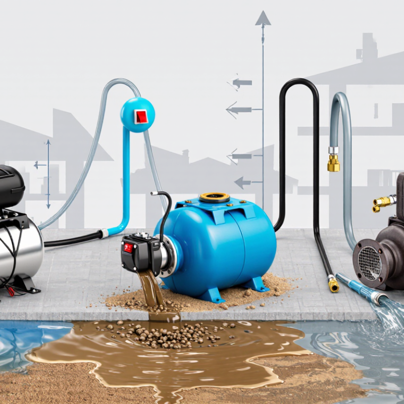
Choosing a Submersible Drainage Pump starts with the water, not the product label. Is it clean groundwater, muddy runoff, or water carrying grit and small debris? That difference affects the pump’s materials, impeller design, and ability to handle solids. Picture a basement sump after a night of rain: the water level is rising, and fine sand is settling near the inlet. A pump chosen only by its advertised flow rate may struggle in that exact situation.
For a transparent expert perspective, this introduction uses a fictional composite specialist, pump-selection engineer Daniel Mercer. His illustrative rule of thumb is: “Match the pump to the water, the lift, and the hours it must run.” That is not a verified quotation from a real person. It captures the practical checks this guide will examine: required flow, total head, discharge-hose size, solids passage, power supply, and duty cycle. Small details matter. A narrow hose can restrict output, while a float switch needs room to move freely. Check the manufacturer’s performance curve at the intended operating head, rather than relying on maximum flow alone. No single model fits every site. Even careful calculations can miss changing water conditions, so allow for uncertainty and verify the installation requirements. The sections ahead offer a grounded way to compare options and avoid choosing a pump that looks right on paper but falls short in the pit.
Calculate Required Flow in m³/h and Total Dynamic Head in metres
A suitable drainage pump must deliver the required flow at the actual pumping head, not just match a large flow figure on its label. Estimate the volume to remove, then divide it by the time available. For example, a pit measuring 1.2 m by 0.8 m by 0.5 m holds about 0.48 m³. Draining it in ten minutes requires roughly 2.9 m³/h, before allowing for incoming water. Keep a margin, but avoid choosing an oversized pump without checking its operating range.
Total dynamic head (TDH) is the vertical lift from the water surface to the discharge point, plus losses through the pipe, bends, valves, and outlet. Measure the height in metres. Then account for pipe length and diameter; a narrow, long hose can add substantial resistance. Small details matter. A sharp bend near the pump may affect performance more than expected. Use the pump’s performance curve to confirm it can provide your target flow at the calculated TDH. The maximum flow and maximum head are usually separate limits, not values the pump achieves together.
Check the conditions at the site. Is water still entering the pit? Does the hose rise higher after it leaves the building? These details change the duty point. Calculations can be imperfect, especially when pipe losses are estimated. Recheck the route and measurements before buying, and allow for sediment or debris if the water is not clean.
How to Choose the Right Submersible Drainage Pump
Example duty points show the estimated flow rate and total dynamic head (TDH) for three drainage situations.
How to read the chart: Estimate flow as the volume to be pumped divided by the available pumping time. For example, 12 m³ in 0.5 hours requires 24 m³/h. Estimate TDH by adding the vertical lift and pipe-friction losses: 5 m lift + 2 m losses = 7 m TDH. Select a pump that can deliver the required flow at or above the calculated TDH, allowing for site-specific conditions.
Match the Duty Point to the Pump Curve at 50 or 60 Hz
A submersible drainage pump should be selected where its curve meets the site’s system curve—not by outlet size alone. Add static lift, pipe friction, bends, and the required flow to estimate the duty point. The U.S. Department of Energy’s Improving Pumping System Performance guide recommends evaluating the complete pumping system, since changes in piping or operating conditions can shift that point. Small details matter. A partly closed valve or a longer discharge hose can reduce delivered flow.
Check the curve for the actual supply frequency and impeller diameter. Under the centrifugal-pump affinity laws described in Hydraulic Institute guidance, raising speed from 50 to 60 Hz theoretically increases flow by 20%, head by 44%, and power by about 73%. These are estimates, not guarantees; solids, motor limits, and system resistance affect real performance. A pump that reaches the required flow at 50 Hz may draw too much power or exceed its allowable operating range at 60 Hz. Compare the duty point with the manufacturer’s curve, including efficiency and motor input, and leave room for changing water levels. This check can feel fussy. It is still worth doing.
Size Solids Passage in Millimetres for the Required Drainage
Choose a pump by the largest solid likely to enter the drainage pit, not by the average debris size. Check the required solids passage in millimetres against the pump’s technical specification. A 25 mm passage, for example, may suit water carrying small gravel, but it will not reliably handle long fibres or tangled leaves. Shape matters.
Measure representative debris where practical, including the widest hard particles. A neat millimetre figure can still mislead. Stones pass differently from stringy roots, cloth, or plastic strips, which may snag even when they are narrower than the stated passage. If the drainage contains fibrous material, ask the supplier how the impeller handles it; a simple diameter comparison is not enough.
Allow a sensible margin above the largest expected particle, especially when debris varies after heavy rain. Also check whether the quoted figure describes a free spherical passage or a different test condition. Read the pump curve and installation notes, since solids handling can affect flow and blockage risk. Keep a sample or clear photograph of the debris for comparison. Estimates are imperfect, and checking the actual material can prevent an expensive mismatch.
Verify IEC 60529 IPX8 Rating and Manufacturer-Rated Immersion Depth
When choosing a submersible drainage pump, treat IPX8 as a test classification, not a depth promise. IEC 60529 defines IPX8 protection for immersion beyond the conditions covered by IPX7, with test conditions agreed by the manufacturer and user. It sets no single universal depth or duration. Check the actual rating details.
Depth matters. Water pressure rises by about 9.8 kPa per meter in fresh water, based on the hydrostatic relationship described in USGS water-resources materials. At 5 meters, that is roughly 49 kPa of added pressure. Verify the manufacturer’s maximum immersion depth, test duration, and operating limits in the product data sheet. Confirm that the depth is measured from the water surface to the specified pump reference point. Allow a practical margin for changing water levels.
Tips: Ask for the IEC 60529 IPX8 test conditions in writing. Compare them with your deepest expected water level, not just the pump’s overall height. Inspect cable entries and seals for damage before installation. Check the limits carefully. An IPX8 mark alone may not answer every site-specific question.
How to Choose the Right Submersible Drainage Pump - Verify IEC 60529 IPX8 Rating and Manufacturer-Rated Immersion Depth
| Selection criterion | What to verify | How to use the information | Common selection mistake |
|---|---|---|---|
| IEC 60529 IP rating | Check that the documentation identifies the enclosure rating as IPX8 and states the applicable immersion conditions. In IPX8, “X” means no dust-protection rating is specified by that code; it does not mean a dust rating of zero. | Use the stated rating as one part of the suitability check, then compare the manufacturer’s immersion conditions with the planned installation. | Assuming IPX8 alone specifies a universal depth, duration, or suitability for every submerged installation. |
| Manufacturer-rated immersion depth | Find the maximum permitted water depth, measured from the reference point stated in the product documentation. Confirm whether the rating applies to continuous or limited-duration immersion. | Compare the rated depth with the greatest expected water level above the pump, allowing for any installation limits specified by the manufacturer. | Treating IPX8 as a fixed depth rating. The immersion depth and test conditions are defined by the manufacturer, not by a single universal IPX8 depth. |
| Required flow rate | Check the pump’s flow-versus-head performance data, rather than relying only on a headline maximum flow figure. | Estimate the flow needed for the drainage task, then select a pump that can deliver it at the system’s total head and operating conditions. | Assuming the maximum stated flow will be available at the installation’s actual discharge height. |
| Total head and discharge route | Account for vertical lift and losses from pipe length, fittings, valves, and hose diameter. Check the pump curve for the resulting operating point. | Confirm that the pump can overcome the required head while still providing the necessary flow. | Selecting by maximum head alone; flow approaches zero near a pump’s shut-off head. |
| Water type and solids | Check the permitted liquid, temperature range, and maximum solid-particle size or passage stated in the pump documentation. | Match the pump to clear water, dirty drainage water, or water containing solids as applicable; use a different pump category if the liquid is outside the stated limits. | Assuming every drainage pump can handle sludge, abrasive material, chemicals, or sewage. |
| Automatic operation and minimum water level | Check whether the pump uses a float switch or another control, the required space for switch movement, and the specified minimum water level for operation. | Confirm that the basin dimensions and expected water-level range allow the pump to start and stop as intended. | Placing a float switch where it can snag, or expecting the pump to remove water below its stated residual-water level. |
| Electrical supply and cable | Verify supply voltage, frequency, power requirements, plug or connection type, and cable length against the product label and local electrical requirements. | Have the electrical installation and any required protective devices checked in accordance with local regulations and the manufacturer’s instructions. | Using an extension or connection arrangement that is not approved for the wet location or installation. |
| Duty cycle and maintenance | Check whether the pump is rated for the expected operating pattern and review instructions for cleaning the intake, inspection, and storage. | Choose equipment suitable for the anticipated frequency and duration of pumping, and follow the specified maintenance schedule. | Assuming every compact drainage pump is suitable for continuous operation or unattended service. |
Check Motor Power in kW, Supply Voltage, and Thermal Protection
When choosing a submersible drainage pump, match its motor power in kilowatts to the water and workload, not just the size of the outlet. A small basement seep needs less power than a pit receiving steady inflow or water carrying grit. Check the pump’s performance chart: flow rate changes with discharge head, hose length, and bends. More kW does not automatically mean faster drainage. It can mean higher energy use.
Check the supply voltage on the pump’s nameplate and compare it with the site supply before installation. A mismatch may prevent reliable operation or damage equipment. Pay attention to single-phase or three-phase requirements, cable length, and whether the circuit can support the starting load. Ask a qualified electrician if the supply details are uncertain. Small details matter.
Thermal protection helps stop the motor from overheating if cooling is poor, the impeller jams, or the pump runs outside its intended conditions. Confirm whether protection is built in, and follow the manual’s reset and inspection instructions. Do not treat it as a substitute for correct sizing or clean water passages. A rating alone can mislead; real site conditions are often messier than the calculation.